top of page
Greensight, Boston
UAV Engineer - in - Training
Live Streaming Drone

Objectives: Make a drone capable of live streaming 4K video
Design Constraints: Ensuring the drone retains its aerodynamics, as well as lightness
What I did:
-
The biggest challenge was designing the drone itself. I was given a basic skeleton of Greensight's Dreamer drone, but I had to ensure the design was aerodynamic while also keeping all components securely attached.
-
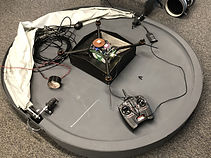
Going into this project, I knew little to nothing about drones and thus, there was a great deal of self teaching involved to find the right answers. I chose to use a fiberglass mounting plate to attach under the drone. I cut the fiberglass to length and modified the battery case using a band and hack saw to fashion it to be completely flat. Once I was satisfied, I aligned the fiberglass to the bottom of the drone (underneath the battery case), marking where the screw holes were and using a drill press to drill in 4 M3 holes. I then arranged all the modems, PCB, GoPro and Streambox in their positions. The components had to be located so wires could be easily soldered onto the drone’s main PCB. I used combinations of a drill press, band saw, miter saw in order to fashion the plate. All wires were wrapped in flexible wire covers and soldered onto the drone.
-
Once the set up was fully functional, I learned how to perform motor and compass calibrations on the drone, pair the controller and receiver and took the drone twice to Devine Golf Course to test and even got the chance to fly it! I believe this project emphasises my ability to teach myself, to struggle with problems and exercise my hands-on skills.
What worked: It was quite amazing to watch an almost completely independent project come to life. Starting a project with no prior knowledge, with complete freedom upon design and taking it from start to finish on my own was something I was extremely grateful for.
Live Streaming Drone
Solar Panel Stands
Objective: Design and build 4 carbon fiber heliostats stands
Design Constraints: Stands had to be lightweight and strong (strong enough to hold the solar panels, along with heliostats). Furthermore, its central of mass had to be perfectly balanced as the stands were to be lifted in air.
What I did:
-
A CAD model for stands existed, yet I was able to optimise the model by increasing structural integrity to ensure it was strong enough to carry its load. I also redesigned the top cross of the stand, allowing it to be manufactured as one seamless part and worked on a linkage piece (made of welded aluminium) to connect the bottom of the stand.
-
Furthermore, I was responsible for manufacturing 4 of these stands. This involved making material judgements in selecting and ordering the carbon fiber of the right specs and then proceeding to build these stands in the machine shop. This involved working with a variety of shop tools.
-
This project taught me a great deal: I took a project from an unusable stage to a successful product - one that reduced material, reduced cost and increased stability through first principles of mechanical engineering. I taught OnShape (CAD software) to myself. I was able to work and see a project from its initial design stages to the final manufacturing. I was able to develop strong hands-on skills, which in turn, allowed me to become a better design engineer. And lastly, I was able to make changes to existing designs and exercise my engineering intuition.
What worked: Manufactured and tested 4 stands successfully! They were 1 meter in height, able to withstand the intended forces and were able to be lifted without tipping. Changing the design of the top cross, redistributing the mass proved to be essential for this process.
[Due to the nature of the project, I am unable to disclose specific details, however, this process proved to be perfect for understanding both design (with OnShape) as well hands-on building to create a successful final product!]
Solar Panel Stand
Mylar Mirrors
Objective: Design inexpensive, lightweight mirrors using Mylar to achieve almost perfect light reflection
Design Constraints: Mirrors have to cost as little as possible, as well as be as light as possible
What I did: Several methods were employed for the design of cheap, lightweight mylar mirrors, suitable for focusing solar energy. In order to construct the mirrors, multiple versions were constructed:
-
Wood frame: Gluing a wooden frame with 4 sides and 2 diagonal pieces was the first method of construction. The mylar was cut to the appropriate length and then tensioned tightly over the frame using double-sided tape. The mylar was then heat-gunned in order for it to shrink and tightly tension over the frame. However, this led to the centre of the mirrors curving due to the diagonal wooden pieces.
-
Wooden frame, offset diagonals: Diagonals were offset ~3cm from the top surface of the frame in order to achieve a flat surface. This design proved to be much more effective.
-
Wooden frame, super-glued Mylar: Alternatively, another rather simple design was tested: where a wood frame was fashioned with offset diagonals and the Mylar was simply super-glued onto the frame and tensioned with a head-gun. This was undoubtedly the lightest and cheapest option but potentially its performance over-time was the only caveat in question.
-
Aluminium frame, wooden dowels: Furthermore, an aluminium frame was tested. At first, ¾” L x ¾” W x 0.125” thick aluminium was used to construct the 4 corners and 2 diagonals, however, this was too heavy and the thickness was reduced to 0.0625”. Here, the mylar was cut with excess length on each side. The excess would fold over the back of the mirror, where 4 circular cut-outs were made and a wooden dowel would slide through the cut-outs. The first tensioning method was using bungee cord in a weaving pattern to tighten opposite sides of the mirror, where the cord would weave tightly around the exposed dowel. This design was further optimised by 3D printing hooks for each portion of exposed dowel and tensioning bungee cord between opposite ends. There were various designs for the hooks, however, after some iterations, 2 closed loops - one for the dowel, one for the knot - was selected.
What worked: As mentioned, the design with an aluminium frame with wooden dowels was chosen. The Mylar was tensioned across the frame and shrunk with a heat gun. The panel was able to reflect up to 95% of the incoming light upon it.
[Due to the nature of the project under GreenSight's wishes, I am unable to share any pictures of my work or provide specificities of the project]
Mylar Mirrors
Other Projects
Remote Piloting

Studied and obtained a Remote Pilot Licence under the FAA's Part 107 exam.
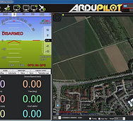
Remote piloted drones all over America and Canada, logging up to over 300 hours using MissionPlanner software
Soldering Batteries

Soldered over 30 batteries for an outside vendor. This project was approximately 4-5 days of understanding electronics and soldering connections to the PCB
Drone Garage

This was my first project at GreenSight! It primarily involved me helping a senior mechanical engineer in the hardware and assembly
Other Projects
bottom of page